I wanted to show what happened on the scanned paper, but it is so filthy and shameful that it’s a horror in general (((In general, I’ll tell you how, after long ordeals and choosing various programs, Google’s Sketchup won.
The program turned out to be so simple and flexible that you can draw almost anything in it. You can download it completely free. The site provides a lot of usefulness in the form of a library of three-dimensional shapes and lessons. From useful I will pay attention to video tutorials. They are in English, but it's not scary.
The translation is of course clumsy in places, but in general you can understand. there would be a desire.
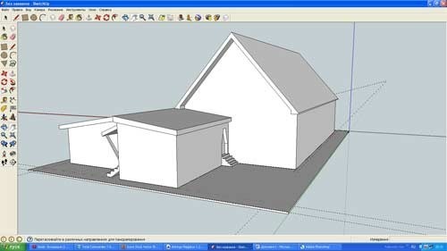
So what happened to me. House from several angles.


In sketchup, you can make a very convenient cut at home, for this there is a special tool. On the cut you can see the location of the rooms. Clockwise starting from the boiler room (the smallest dead-end room with a separate entrance from the street), then two bedrooms, a bathroom just below, even lower a living room in which it will later be decided to make an additional window, to the left of the vestibule to isolate the house from winter drafts, even more to the left is the third a bedroom and where a staircase is drawn - a kitchen with a separate, summer exit not a veranda. The staircase is just drawn on the project, in real life it will not be, as well as the second floor.
3D models of projects Karkas Info. © CC BY Vladimir Pustokhod, 2016
Many of our customers and website visitors want to delve into the design of their future home in detail, but at the same time, few people work in CAD programs - for the average user they are too cumbersome, complex and inconvenient ... and often require powerful workstations.
Therefore, the KARKAS INFO team offers additional service— translation of the frame model of your house in SketchUp.
By downloading this free program to your computer, or a program for viewing these files on a tablet or phone, you can view the frame model and its nodes in detail from all sides, in any convenient place.
A full-fledged frame model will allow you to specify the dimensions, interface nodes on the spot, and, if desired, try to make small changes yourself.
 Isolate model layers. © CC BY Vladimir Pustokhod, 2016
 Our 3D model is not just a three-dimensional model of the frame - it is a model broken into layers: strapping, bottom floor, top floor, rafters, etc. which, if necessary, this moment Layers can be turned on or off, leaving only what you are currently working on, such as the outer walls of the ground floor, allowing you to see them in great detail.
 Frame wall elements. © CC BY Vladimir Pustokhod, 2016
 Having a model of the house and having mastered the basic skills of working in SketchUp, you can try to design yourself, for example, a ventilation system, or create an electrical diagram for the rooms of the house.
 Bottom cover. © CC BY Vladimir Pustokhod, 2016
 Even if you are not the original customer of the project, we can prepare for you a 3D model of the load-bearing frame of any of the projects presented on the site (subject to a number of conditions).
You, dear readers, have learned that the Google SketchUp program is designed for quick 3D design of architectural objects, landscape design, interiors, etc. What exactly can be created with Google SketchUp 8.0, and where can it be used at home? Consider one of the examples of using the program to create a project for the reconstruction of the roof of a residential building. The project provides for the replacement of asbestos-cement sheets with metal tiles with the addition of additional structural elements roofs.
The changes were caused by the expansion of the living space due to the construction of another attic-type room in the attic, and for better illumination of the room, it is necessary to make dormer windows in the roof. At the same time, it should be taken into account that the location and design of the dormer windows should not disturb the overall harmony of the existing building.
In this case, the Google SketchUp program is simply indispensable, because. allows you to quickly implement the author's ideas without long training and make the necessary adjustments to the built-in elements of the roof, choose a combination of colors for the walls and roof. But, before you begin to perform all the tasks, you first need to have a 3D project of an existing house.

Let's consider in this example the sequence in which the 3D model of the house was built, on which the conceived ideas will subsequently be implemented.

To begin with, the construction of the foundation on which the house will stand was carried out with tools Rectangle and Pull/Push. The dimensions of the rectangle were entered from the keyboard in the lower right window Dimension indicators.

Tool Roulette marking lines were laid off from the edges of the base.

Along the contour of marking lines with a tool Rectangle a rectangle was built with sides equal to the length and width of the house, and with a tool Pull/Push he pulled up. Please note that during model building, the dimensions are reflected in the window Dimension indicators and can always be corrected by entering the desired numbers from the keyboard.

Then Roulette the ridge marking line and the marking line of the transition from the roof of the house to the roof of the fence were postponed. Tool Line two lines were drawn along the marking parallel to the green axis, after which the tool Move the ridge line rose up, and the extreme line of the roof slope of the fence fell down.

The transition from the closed porch to the garage and the roof overhangs were done with tools Roulette, Line and pushed - Pull/Push.
The same tools were used to display the buildings adjacent to the opposite side of the house.

On the facade of the building, the design of the porch was carried out. The contours were drawn with tools Rectangle, Line and Arc, and unnecessary segments were removed Eraser. The entrance was pressed with a tool Pull/Push, and the upper lines of inclined surfaces - with a tool moving.

Then Roulette marking lines were laid aside for building windows on the facade. Tool Rectangle the contour of the window was performed, and the tool Bias- Frame outline.

The marking lines marked the bindings of the frames, and the tool Rectangle six rectangles were built inside the contours of the marking lines. These rectangles depicted the contours of the glass in the frame.

Tool Pull/Push the window casing stretched outward, and the contours of the glass were slightly pressed inwards. The finished window image was selected with the tool Choose. With this tool, when the mouse button is pressed, the window is enclosed in a rectangle. After releasing the mouse button, all window outlines turn blue. Next, holding down the button on the keyboard ctrl, the mouse pointer captures the selected window and moves a copy of the window to the space allotted to it. As you can see, everything is simple, and you do not need to draw repeated elements repeatedly.

Similarly, the construction of windows on the side wall of the house and the attic was carried out.
In one of the next issues on the site http: // site, the story of the creation of the first project on Google SketchUp will be continued.
Post Views:
1 611
This powerful and easy-to-learn (and free!) software will help you speed up your creativity so you can design your products faster than ever.
I prefer working with wood (no pencil here) than painting. However, in starting work without drawings to guide me, I run the risk of only disappointment and waste of material. I recently discovered something better than paper scribbled and insecure. A free program called Google SketchUp received a lot of positive feedback on online forums dedicated to software. People of all skill levels download SketchUp and start using it the same day. So I downloaded the program and gave myself a crash course in joinery design, using an existing project, a table napkin holder, to hone my skills. Of course, there were moments when I failed (although they were not as many as in my first experience with a tenoner). But after a few hours, everything became clear, and I was able to move on to designing a bookcase and bedside table. Now you can talk about what I learned and what you need to know in order to achieve the first results.
Bob Wilson, technical editor
Download and Learn SketchUp in Five Steps
1 Go to http://www.sketchup.com/download. Download free version SketchUp by following the instructions that appear. Then install the program.
2 Print out the "Quick Reference Map" found in the Help menu of the site. It describes how to activate different instruments programs.
3 Go to the "Video Tutorials" section and open the "For new SketchUp users" link in it. Watch videos that show the program in action.
4 Now you can directly learn how to work with the program. Take your time to go through the step-by-step tutorial "Introduction to Sketchup". Then see the "Start a Drawing" guide (in three parts) contained in the same section of the site.
5 Before starting to develop carpentry projects, spend a few hours simply getting to know the program's capabilities.
New approach to design
SketchUp is designed for users who prefer to design rather than learn computer programs. So, just one click of the mouse allows you to turn a two-dimensional figure into a three-dimensional object, and a couple more clicks - to create a copy of this object. You can even apply different wood textures to the model to decide which material to use to make it look better, such as walnut or maple.
Sometimes it feels like SketchUp is reading your mind. For example, if you want to find the midpoint of a line, " analytical center» of the program will issue an appropriate message as soon as the cursor approaches this point. This applies to other points in your drawing as well.
In fact, no program will think for you. The program will not issue any warnings if the spike in the joint is 6 mm longer than necessary, and will not criticize the proportions of the cabinet 30 cm wide and 2.4 m high. In addition, if you plan to use the drawing prepared in SketchUp when working on product, it must be accurate and detailed.

Compared to SketchUp's stock colors and textures, the free IDX Renditioner Express add-on (idx-design.com) is a significant improvement. It gives realism and allows you to add natural or artificial lighting to get an idea of how your project will look in real life. All this is done right in SketchUp.
Mastering the basics of SketchUp
Download and install Google SketchUp* on your computer using the instructions on the previous page. Follow the instructions on the screen during the installation process.
* In preparing this article, I usedsketch up version 6. The later version you downloaded may look different. All versions have options forWindows and for Mae. To find out if the new version will work on your computer, check out « requirementssketch up to hardware and software" located in the "Downloads" section of the sitesketchcliup. gooyle. com.
The first time you launch the program, it will ask you to set the default settings. Select the Product Design & Woodworking template and the unit of measurement is millimeters. You can change these settings later with the menu command Window -» Options.(If you are unfamiliar with this terminology, refer to the image of the program window, top center.)
Next, learn the basics of working in the program using guides from Google. Go to sections Training courses- Video tutorials and Tutorials - Step by Step Tutorials and work through the lessons in them, starting with the "For New SketchUp Users" lessons. These guides will take you step by step from getting started with the program to creating complex models. For this article, you will need to complete the tutorials up to "For Users Familiar with SketchUp". If you want to see on-screen tooltips depicting the action of different tools, turn on the function Oki" Textbook. Get into the habit of using the time-saving mouse commands and keyboard shortcuts listed on the right from the start. By learning how to create 3D objects and move around them, you will be ready to apply these skills to your carpentry project.
An example of a robot is a napkin holder
To show how to model a real carpentry product in SketchUp, we used a napkin holder project as a model. This means that we already have the dimensions of all the parts. When designing a product from scratch, first determine its overall dimensions on paper or with a preliminary model that you can then modify. It's time to turn on your computer, open SketchUp, and get started.
Learning Modeling in SketchUp by Example

1. To model a napkin holder, first create a new modeling window using the Product Design and Woodworking template. Using Dialog Box Model Data window, set the precision to 1 mm. Now draw a rectangle and delete it. Note that the tooltips in the status bar change depending on the selected tool.

2. Plot the distances from the red and green axes using the tool Roulette, to create guide lines for the legs and top rail (or enter their values in the control box dimensions). Draw a rectangle along these guides using the tool Rectangle.

3. Using a tool Roulette set guide points on one of the long sides of the rectangle at a distance of 10 mm from the corners (if necessary, increase the viewing angle). Using the tool Arc, click on the guide points and slowly move the mouse pointer until the end of the arc is at the quarter circle position.

4. Using a tool Choice select one of the straight sides of the resulting sector. key Delete(not eraser) delete it and the area adjacent to it, then delete the other line. To duplicate this shape for the legs, you divide the rectangle and use the Move with key pressed Shift(on Mac computers - by pressing Option). After you have finished with the outlines of the legs and rail, extrude them with the tool Pull/Push up to a thickness of 13 mm.

5. After drawing the new guide lines and drawing a rectangle for the support, mark parallel curves using the guide points and the tool Arc. Select and delete the corners to get an arc shape.

6. Using the tool lines mark the intersections of the rectangles forming the notches with the arc and delete these lines. Next, finish the meadow shape and make a copy of it. On one of the parts, draw groove lines using guide lines and a tool Line.

7. Using a tool Pull / Push pull both supports up to a thickness of 13 mm. To create grooves in the posts for the posts, lower the areas between the lines drawn on the stage 6. When the details are ready, delete the guide lines.

8. SketchUp doesn't draw parabolic curves, only circle fragments. To draw this arc, add guide points where indicated and use the Arc slowly draw the curve to the desired shape. Remove excess area and extend the part to a thickness of 13mm.

9. Sometimes you need to get a mirror image of a part, as in the case of a napkin holder stand. Using the tool Move and holding the key control(on the Mac computers — Option), create a duplicate rack and keep the selection. In the context menu, select the command Flip To - Component Red Axis(in this case) to create a mirror copy.

10. To round the edges, set the guide points on two adjacent lines of one of the ends at a distance of 3 mm from the corner. Draw a quarter-circle arc between these points. By zooming in, make sure the arc does not go beyond the straight lines. Select a corner with the tool Teeny/Talk drag the corner to the opposite end where it should disappear. You see several closely spaced parallel lines because SketchUp doesn't draw perfect curves, but rather forms them from a series of flat faces.

11. To prepare the parts for assembly, first turn them into position with the tool Turn. By rotating the part, check that it is installed along the desired axis, in this case blue. When a match is reached, the program will display the corresponding caption.

12. Since the prepared drawings are intended for cutting out parts on them, it is useful to put down the dimensions using the tool Size indicator.(Dimensions will not be placed on copies of parts.) To group the faces and edges that form each of the parts, triple-click one of the part's surfaces and select Create Group from the shortcut menu.

13. Now let's virtually assemble our product. The distance between the legs of the napkin holder is 102mm, so create two parallel guide lines at the specified distance from each other and one perpendicular guide line to align the legs. When aligning grouped surfaces and part edges, ignore the blue selection borders that indicate the part—they cannot be aligned with guide lines. Zoom in on the guides and drag the leg face to one of the guide lines, and the end of the leg to the perpendicular guide line. 11Check if they are installed correctly with Roulettes.A measurement result preceded by a tilde sign (~) indicates that the distance was measured approximately and the part may not be set accurately.

14. Use guide points and intersecting lines of grouped parts to precisely fit one part to another. For example, the napkin holder supports are installed at a distance of 6 mm from the ends of the legs. Use Roulette to set a guide point at a distance of 6 mm from the end of the leg. Using the tool move, pick up a copy of the end support and roughly set it in place. Move the cursor over the corner of the cut and move the support until its corner matches the guide point. Check the position of the support on the opposite leg. You can use this technique to connect the rails to the end support.

15. If you want the parts to remain connected to each other, group them in the same way as you did with the top rail earlier, using the command To create a group in the context menu. To leave a gap of 1.5 mm between the rail and the posts at both ends of the napkin holder, use the tool Roulette put a guide point on the bottom edge of the rail, stepping back 1.5 mm from its end. While inserting the clamp with rail between the posts on both sides of the napkin holder, bring the guide point to the edge of the post. Now using the tools Orbit and Panorama, you can view your finished model from different angles.

16. The bright colors used to distinguish details do not allow visualization of the finished project. Use the wood texture swatches provided in the dialog box Color, or download the texture pack from woodmagazine.com/woodgrain. Right-click on each of the grouped parts and select the command from the context menu Disconnect. Immediately apply the texture with the Fill tool, and group again.

17. Maple and walnut textures (the species recommended in the napkin holder project description) will give the model a more realistic look.


Only lovers will survive
Features of advertising aimed at children
retouching old photos in photoshop retouching old photos
What is an NPO: decoding, definition of goals, types of activities Does a non-profit organization have the right
Gleb Nikitin First Deputy