 There are many games in which, for example, the number of points scored by the player. determined by the roll of a dice. It is not difficult to make an electronic "cube" random number generator. Schemes of such generators and descriptions are found in amateur radio literature.
Recently, the game system "Age of Battles" has gained popularity. For it, figures of warriors of the most interesting historical eras, siege weapons, elements of terrain and fortresses are produced on a scale of 1:72. Now the player can, with a certain degree of historical realism, try himself in the place of Miltiades or one of the Napoleonic marshals.
The rules of the "Age of Battles" are quite complicated. The probability of many events - hitting or missing an archer, breaking through armor, etc. is determined using a twenty-sided (!) Cube. It is difficult to replace it in case of loss or damage. In addition, when the cube is on a soft surface (for example, on a carpet), it becomes not so easy to clearly determine its upper face. In addition, the classic six-sided die is also used for a number of purposes in the game. All this prompted me to develop the design of an electronic "cube" capable of working both as a 20- and as a 6-sided one.
However, the implementation of this seemingly simple task was not easy. The required results were achieved only on the fourth version of the device, which is offered to the attention of readers. I think the design will be interesting and convenient for radio electronics - lovers of table battles.
The principle of operation of the device is traditional: a master multivibrator with a frequency of several kilohertz is assembled on the elements D1.3, D1.4. When you press the S1 button, a high logic level is applied to pin 5 of element D1.2, and the multivibrator pulses go to counter D2. When the button is released, the counter stops in some random position, which is displayed. To transfer numbers up to 20, 5 binary digits are needed, while most TTL (transistor-transistor logic) counters are four-bit. Therefore, a K176IE2 CMOS chip is used here. This counter is economical, it has just 5 digits in binary counting mode. and moderate speed provides good noise immunity. For information about the control inputs of the D2 chip. Logic 1 is applied to them. Input E (pin 2) - switch "account / load", the counting mode is selected. Input 2/10 (pin 1) - switch for binary or decimal counting mode, binary mode is selected.

1 - front panel; 2 - decorative overlay; 3 - LED (20 pieces); 4 - printed circuit board; 5 -Z-shaped bracket for installing the switch (steel plate s1); 6 - fixing the board and bracket to the case (M3 bolt with nut, 2 sets); S1 - switch; S2 - mode switch
Most of these devices use the classic output to digital indicators. However, it creates a lot of problems, in particular due to the fact that there the score starts from 0, and not from 1, as is customary in game dice. The scheme for selecting the counting ranges is also cumbersome. Therefore, I had to stop at the positional indication. But the applied microcircuit decodes only A binary digits and, accordingly, has 16 output channels. What about numbers from 17 to 20? The classic solution is to install another decoder is cumbersome and uneconomical, and most importantly, the outputs of the CMOS counter simply cannot pull two address inputs of "oak" TTL microcircuits at once. But what if you use the D3 decoder "for the second time"? Thanks to element D1.1, we have the most significant bit of the address, both in direct and inverse form. Now it’s easy, using transistors VT1, VT2, to turn on desired group LEDs. depending on the range of numbers. There are three of these groups: HL 1-6 operate at 0 in the fifth binary digit, HL 17-20 - at 1, but HL 7-16 can be powered continuously. The amount of current through the LEDs is determined by the resistors R6, R8, R9. In the device, it is about 7 mA. This provides sufficient brightness of the indication and at the same time does not overload even the low-power TTLSH (transistor-transistor logic with a Schottky barrier) K155IDZ chip. When using LEDs of a new generation on heterostructures, the resistance of the mentioned resistors can be doubled or tripled.
The choice of the mode is carried out by the switch S2. As soon as the score reaches the “forbidden” 7 or 21 points, a log is sent through R11 to the input of the cascade on VT3. 0. The signal is inverted and the counter reset input is applied. In addition to the logical function, the VT3 cascade also performs one more function. The point is that one of the problems with joint work CMOS and TTL ICs is not high enough logic voltage 1 of the latter. Here it is amplified almost to the supply voltage. There is one more feature in the logic of this node: in the accepted decoding system, the number 21 is “reflected” on the number 5, which can lead to a premature reset of the counter. Therefore, in 20-grain mode, an inverted fifth digit of the counter is supplied to VT3 through R10. Due to this, with numbers less than 16, the transistor opens - and at the reset input, the counter will be log.0. regardless of other signals. During the countdown (when the S1 button is pressed), the LEDs of the selected range are slightly illuminated by current pulses “running” through them. This allows you to verify that the circuit and all LEDs are working.
When using a dual-mode e-dice, the following error is possible, working in 6-sided mode when a 20-sided one is needed. As a result, it may turn out that a powerful ballista will categorically refuse to penetrate the armor of infantrymen. Therefore, an effective indication of the 6-point mode is necessary. No tricks with digital indicators can eliminate the error due to absent-mindedness. In the proposed design, the indication of the 6-sided mode is carried out by the HL7 LED, which is a kind of visual limiter of the included reading range. It is impossible not to notice that instead of one desired one, two LEDs are lit at once, and this is another advantage of the adopted positional indication system. In order not to short-circuit the pin to the ground. 7D3, it is separated from the switch by a diode.


The 5V supply voltage stabilizer (DA1 chip) is installed directly on the device board. Due to this, almost any network adapters with an output voltage of 9 - 12 V can be used to power the device, since the current consumption does not exceed 80 mA. An acceptable option is 2 - 3 batteries 336 connected in series. But in this case, it will be necessary to introduce a power switch into the design.
About the details: transistors VT1, VT2 can be any of the KT361, KT203, VT3 series - n-p-n structures, KT315, KT301, KT312 series. Chip K176LA7 is replaceable by K561LA7. D3 - 155th or 1533rd series. These replacements do not require changes to the printed circuit wiring. Only K1533IDZ can be in a narrower package, but the pinout is the same.
However, it may be difficult to obtain the necessary microcircuits. Almost all the "logic" sold now in stores - 1988 - 1992. release, and these stocks are running out. It remains to replace the microcircuits with others of a similar purpose. So, as D2, you can use the K176IE1 chip - a simple 6-bit binary counter. As D1 - a chip with three NAND elements. In this case, the element D1.2 is excluded, the counting permission signal is sent to one of the inputs D1.3. The use of D1.2 is good in that it also generates multivibrator pulses. But the counters will work in such an abbreviated version of the circuit.
I remind you of the need to follow the rules for mounting semiconductor devices: CMOS chips should be stored wrapped in foil, soldered with a low-voltage soldering iron with a grounded tip. This is especially true of microcircuits of early development, when designers were reluctant to install protection elements due to a decrease in performance. In cases where soldered or somewhat suspicious microcircuits are used, use sockets. LEDs, especially in a plastic case, should be soldered no closer than 10 mm from the case, preferably using an additional heat sink.
Switch S2 - any with three groups of contacts for switching. In the device under consideration, 2 P2K buttons with dependent fixation are used. Its pin contacts are shortened on one side. Button S1 - type KM 1-1 or similar. Readers can choose the colors of the LEDs (for example, the first 6 are of a different color) at their discretion. Capacitors C3, C4 - any ceramic, suitable in size.
Design. Since the device did not use super technologies such as photolithography and metallization of holes, it was not possible to separate all the conductors with printed wiring. The remaining connections - 3 and 4 digits were soldered with a mounting wire (MGTF is most convenient). On sharply sharpened tweezers, a ring is formed and put on the output of the microcircuit. It remains only to touch it with a soldering iron. Similarly, most of the wires to the LEDs are also soldered directly to the D3 pins, especially since the indicators in the device case are on the foil side.
A radiator made of a small aluminum plate is screwed to DA1. In the case opposite it, it is desirable to make ventilation holes. As for the case and the front panel of the electronic "cube", they are made of boxes cut from the back plastic wall of an old TV.

The board is located with the parts down and is attached to the case using a rectangular stand and two M3 bolts with countersunk heads. This stand, like the S2 mounts, is best made of polystyrene, which allows them to be glued to the body. After that, a metal bracket with the S1 button is screwed to the board with two nuts. The button is located so that when you press the case, it works.
Make sure there are no solder pools or short circuits between the tracks. Check the polarity of all LEDs. Properly assembled from serviceable parts, the device does not require adjustment. The final check of the correct assembly and functioning of the device can be carried out very effectively: connect a capacitor with a capacity of about 0.33 microfarads in parallel with C1. Press S1 If everything is assembled correctly. then you will be able to observe the beautiful effect of running lights in the range selected by switch S2.
The front panel of the device is painted with golden bronze metallic enamel and stylized as an ancient Greek shield - hoplon.
May Pallas Athena (the Greek mythical goddess of war and victory, as well as wisdom, knowledge, arts and crafts) help you in technical creativity and in battle!
A. LISOV. Ivanovo
This device is based on a random number generator and is designed to be used as a game (for example, in dice, or as a cube in logic games), and it can also be used to determine the winner in any competition by drawing lots...
The design is very simple, and repeatable by almost any novice radio amateur who has the least experience with a soldering iron and knows the specifics of soldering microcircuits. It is as follows:
1) The tip of the soldering iron must be grounded
2) Do not heat the output of the microcircuit for longer than 5-8 seconds
The first item can be omitted if the microcircuit is not afraid of static (but this does not apply to MK).
So, here is the actual device diagram:
I immediately focus on the absence of current-limiting resistors connected in series with the LEDs. In this circuit, they are not needed, since at a supply voltage of 3.7V, a relatively small current flows through the LEDs, which the microcontroller is able to withstand (but if you still want to play it safe, then there is enough space on the board to turn on resistors in series with the LEDs in smd execution).
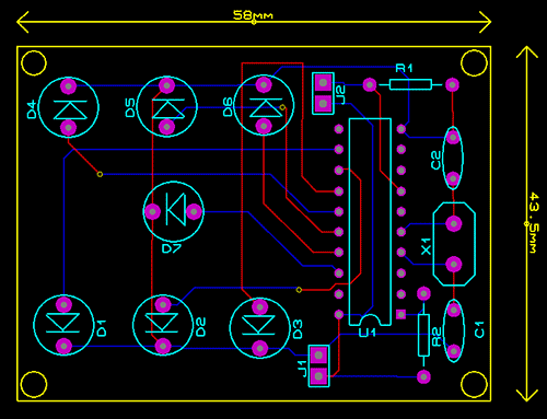
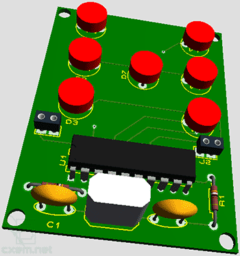
As you can see, the dimensions of the board are quite modest (6 x 4.5 cm). If you use a printed circuit board with the layout shown in this article, then appearance the fee collected will be as follows:
Since in this design the board is made in a double-sided version, the procedure for soldering the socket for the microcontroller may turn out to be problematic. In my practice, I use this method of connecting two layers of the board:
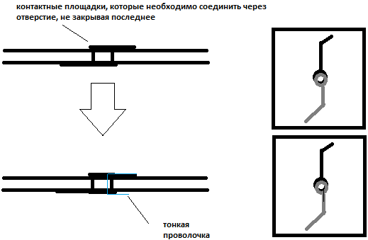
This method is well suited for connecting low-power printed conductors, as well as where the number of connections of this type is small, otherwise it is very difficult to solder all this.
Now about the firmware. I developed a program for MK in the environment (the project is attached to the article, there is also a project in PROTEUS). The program works as follows: when power is applied to the MK, the program starts and waits for a button to be pressed. As soon as the button is pressed, the gsch variable (of type byte) is called and a value is assigned to it (this is a software RNG). Next, the generated number is evaluated, with an interval of 42 bits (if the number<=42 битам, тогда на кубике высвечивается одна точка, если число больше 42, но меньше 84, то высвечивается две точки и т.д. Так же после отпускания кнопки число будет светиться до следующего нажатия.
Now about fuse bits:
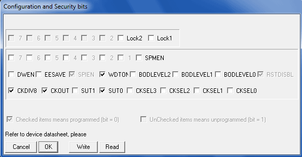
This is how their installation window looks in the program.
Parts, replacements. As a control element, I used an AVR family microcontroller, ATTINY2313, a quartz resonator should be taken at a frequency of 8MHz, capacitors with a capacity of 22-33 pF, as for LEDs, they should be low-power for a nominal voltage of 2V.
Below you can download the source codes, firmware, software, project in and
- 20.09.2014
The proposed self-generating SMPS (switching power supply) has small dimensions and high efficiency. Its peculiarity is that the magnetic circuit of the pulse transformer works with entry into the saturation region. When designing self-generating SMPSs, in most cases, a powerful transformer is used in linear mode, and a low-power switching transformer is used in magnetic circuit saturation mode. Separate windings of these ...
- 17.03.2017
The multivibrator circuit on NAND elements is shown in Figure 1. The circuit has two states: in one state, the element DD1.1 is closed, and DD1.2 is open, in the other, everything happens the other way around. For example, if the element DD1.1 is closed, DD1.2 is open, while the capacitor C2 is charged by the output current of the element DD1.1 flowing through the resistor R2. Voltage on...
- 22.06.2015
Stationary interchangeable measuring shunts 75ShIS (hereinafter referred to as shunts), with a rated voltage drop of 75 mV, are designed to expand the measurement ranges of direct current indicating recording devices used at various objects in the field of defense, industrial safety. DESCRIPTION Structurally, the shunts are made in the form of manganin jumpers, connected by soldering with brass or copper tips, mounted on a plastic base ...
- 06.10.2014
This is a simple signal strength indicator for audio equipment, the circuit is adapted to different needs of users. Can be adapted to different input signal levels - TR1 (input voltage level adjustment), TR2 (gain adjustment). Principle of operation: after amplifying the op-amp on TL017, the signal is rectified by diodes D1-D2 (in the future, only the positive half-wave of the signal is used), then the signal ...
The construction described below performs the functions of a game die, but has the advantage over it that it does not require a real die to be thrown on a horizontal surface. The basis of the device is an indicator consisting of seven LEDs HL1-HL7 (Fig. 1), arranged so as to highlight the configuration of any of the six faces of the cube.
In accordance with the block diagram (Fig. 2), the device contains a pulse generator, a counter, a code converter (decoder) and the aforementioned LED indicator.

The schematic diagram of the device is shown in fig. 3. On the elements DD1.1-DD1.3 of the DD1 microcircuit, a pulse generator is assembled according to the standard scheme. The pulses are fed to the input C2 (output 1) of the counter, made on the chip DD2. Thanks to the feedback to the inputs & and R (pins 3 and 2), the counter works with a conversion factor of 6. Diodes VD1-VD5, element DD1.4 and elements of the DD3 chip form a binary code converter into the "code of the faces of the cube". The signals of the latter are fed to the LEDs HL1-HL7, indicating the dropped number. Resistors R2-R8 are installed to limit the current through the LEDs.
The device works like this: while the contacts of the SB1 pushbutton switch are open, the generator sends clock pulses to the counter and the LEDs on the indicator switch with high frequency, indicating the "edges of the cube" sequentially from 1 to 6. As soon as the SB1 contacts are closed, pressing the button, the generation of pulses will stop . At the outputs of the DD2 chip, a number in binary code will be fixed, and on the indicator - the corresponding "dropped number". Thus, to "start" the cube, you must turn it on with switch SA1, and to stop it, press the switch button SB1.
Now let's say a few words about the design and details of the device: DD1 and DD3 microcircuits - K155LAZ, K555LAZ; DD2 - K155IE5, K555IE5; diodes VD1 - VD5 - KD522B or series KD102, KD103; resistors R2-R8 any, suitable in size, with a nominal value of 120 to 470 ohms (the brightness of the indicator diodes depends on their resistance); capacitor C1 must be ceramic, it is permissible to replace it with an oxide capacitance of 1 ... 2 μF. In the absence of such capacitors, two oxide polar (electrolytic) capacitors can be used by connecting them in series, "towards" each other.
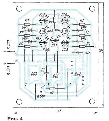
All parts of the electronic cube, except for the pushbutton switches SA1, SB1 and the battery, are mounted on a printed circuit board measuring 57x70 mm, a sketch of which is shown in fig. four.
The whole structure is placed in a plastic case of suitable dimensions (Fig. 5). The device receives power from a flat battery with a voltage of 4.5 V. The current consumption when using K155 series microcircuits is approximately 40 mA.

In conclusion - about expanding the gaming capabilities and changing the layout of the cube. If the capacitance of the capacitor C1 is increased to 50-100 μF, and instead of the constant resistor R1, a variable one with a large resistance is installed, then the switching frequency of the indicator can be changed over a wide range. Then, at low values of the resistance of the resistor R1, the dropped value on the indicator is random (the device performs the function of a cube). With large values of the resistance of the resistor R1, the switching frequency of the "faces of the cube" decreases, which will allow you to visually control and fix the number on the indicator (reaction games).
The device can be significantly simplified if the counter is excluded from the block diagram (see Fig. 2) and the generator pulses are immediately converted into indicator codes. This can be achieved using three D-flip-flops, for example, those included in the K155TM8 chip, by connecting them to a ring counter. The scheme of the modified device is shown in fig. 6, and the timing diagram of the outputs of triggers (points A, B, C and D) - in fig. 7.

The pulse generator is assembled on the logic elements of the DD1 chip. Rectangular pulses from its output (pin 8) are fed to the counting input of the DD2 chip (pin 9). On the front of the fourth pulse, thanks to the feedback through the DD1.4 element, the triggers are reset to zero (at the beginning of the seventh cycle). Otherwise, the operation of the device is the same as the previous one. The printed circuit board for this version of the electronic cube was not developed.
This device is based on a random number generator and is designed to be used as a game (for example, in dice, or as a cube in logic games), and it can also be used to determine the winner in any competition by drawing lots ...
The design is very simple, and repeatable by almost any novice radio amateur who has the least experience with a soldering iron and knows the specifics of soldering microcircuits. It is as follows:
1) The tip of the soldering iron must be grounded
2) Do not heat the output of the microcircuit for longer than 5-8 seconds
The first item can be omitted if the microcircuit is not afraid of static (but this does not apply to MK).
So, here is the actual device diagram:
I immediately focus on the absence of current-limiting resistors connected in series with the LEDs. In this circuit, they are not needed, since at a supply voltage of 3.7V, a relatively small current flows through the LEDs, which the microcontroller is able to withstand (but if you still want to play it safe, then there is enough space on the board to turn on resistors in series with the LEDs in smd execution).
Device board:

As you can see, the dimensions of the board are quite modest (6 x 4.5 cm). If you use a printed circuit board with the topology shown in this article, then the appearance of the assembled board will be as follows:

Since in this design the board is made in a double-sided version, the procedure for soldering the socket for the microcontroller may turn out to be problematic. In my practice, I use this method of connecting two layers of the board:

This method is well suited for connecting low-power printed conductors, as well as where the number of connections of this type is small, otherwise it is very difficult to solder all this.
Now about the firmware. I developed a program for MK in the Flowcode environment (the project is attached to the article, there is also a project in PROTEUS). The program works as follows: when power is applied to the MK, the program starts and waits for a button to be pressed. As soon as the button is pressed, the gsch variable (byte type) is called and the value is assigned to it
Now about fuse bits:

This is how their installation window looks like in the PonyProg2000 program.
Parts, replacements. As a control element, I used an AVR family microcontroller, ATTINY2313, a quartz resonator should be taken at a frequency of 8MHz, capacitors with a capacity of 22-33 pF, as for LEDs, they should be low-power for a nominal voltage of 2V.


For beginners: breeding a broiler at home Boiled water for broilers
Only lovers will survive
Features of advertising aimed at children
retouching old photos in photoshop retouching old photos
What is an NPO: decoding, definition of goals, types of activities Does a non-profit organization have the right